One of them is Motion Sensing.
The PIR Motion Sensor from SparkFun looked good at first but I was concerned with the problems it seemed to have running at 3.3v.

All the other PIR Sensors on eBay seemed to have the same setup with some onboard voltage regulator. 1.7v Voltage Dropout on these regulators prevent an already regulated 3.3v source from powering it out-of-the-box. Or so I thought...
The even more expensive sensor from Parallax looked fine but at $11 it was going to add up with a lot of my sensors. I felt a little more comfortable tinkering with a cheap sensor from China than the others so I ordered two sensors from two different eBay merchants at around $3.

Unreliable at 3.3v
Hooking these sensors up to my Programmable XBee with a did not go as well as I had hoped. The sensor simply didn't work with a 3.3v VCC source just like the SparkFun sensor. The signal was wildly erratic as if someone was moving randomly in front of the sensor:#3064 TMP102=22.19 Door=CLOSED Motion=NO
#3068 TMP102=22.19 Door=CLOSED Motion=NO
ALARM: Motion
#3072 TMP102=22.19 Door=CLOSED Motion=NO
#3076 TMP102=22.19 Door=CLOSED Motion=YES
ALARM: Motion
#3080 TMP102=22.19 Door=CLOSED Motion=NO
ALARM: Motion
#3084 TMP102=22.25 Door=CLOSED Motion=YES
#3088 TMP102=22.25 Door=CLOSED Motion=YES
ALARM: Motion
#3092 TMP102=22.25 Door=CLOSED Motion=YES
#3096 TMP102=22.19 Door=CLOSED Motion=YES
Reliable but useless at 5v
Connecting it to a 5v source fixed the problem just like others:#3872 TMP102=22.19 Door=CLOSED Motion=NO
#3876 TMP102=22.19 Door=CLOSED Motion=NO
#3880 TMP102=22.19 Door=CLOSED Motion=NO
ALARM: Motion
#3884 TMP102=22.19 Door=CLOSED Motion=YES
#3888 TMP102=22.19 Door=CLOSED Motion=NO
#3892 TMP102=22.19 Door=CLOSED Motion=NO
#3896 TMP102=22.19 Door=CLOSED Motion=NO
#3900 TMP102=22.19 Door=CLOSED Motion=NO
#3904 TMP102=22.25 Door=CLOSED Motion=NO
However this makes it a borderline unusable sensor since I won't have 5v on my final module. Fortunately I stumbled on an interesting hack that most likely will work fine at 3.3v permanently.
Knowing enough to cause damage
I'm actually just getting back to hardware tinkering after a 15 year hiatus doing software. This reminds me of learning how to code by just messing with source and seeing what happens.
After probing the voltage regulator I confirmed that the sensor had a 7133-1 regulator which does have a 1.7v Voltage Dropout. That's sad since I was hoping to be lucky with something closer to Parallax's design that can take input down to about 3v.
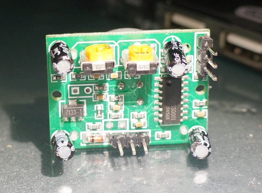
Probing around with the multimeter I confirmed the 5v in and 3.3v out on the 7133 regulator. I also found a pure 3.3v at the lower right capacity's outer leg which rings right with what I just read about voltage regulators and noise in SparkFun's Beginning Embedded Electronics. It looked like that capacitor would be an easier point to inject my already clean 3.3v power into the sensor than shorting out the regulator.
Easier 3.3v access?
Looking at the backside of the circuit board I could see a small trace from the newly discovered 3.3v capacitor's positive pin crossing over to... the H-pin? After another attempt at tracking down a schematic I found something similar over at openimpulse.com.
Their schematic looked showed the sensor's 3-pin was connected directly to V-out from the regulator and the whole rest of the 3.3v trunk! Its main purpose is to bring the BISS0001's A-line either high or low but let's use it as a 3.3v VCC instead.

Final 3.3v Hack and No Damage
Probing the three pins I found one of them being exactly 3.3v. After moving over the gray cable over from a 5v to a 3.3v source, I plugged the other end into pin-3. The sensor worked perfectly and reliably, just as when it was powered by 5v!
3.3v motion detecting PIR sensor done without any soldering.
3.3v motion detecting PIR sensor done without any soldering.

Sheer brilliance! This saves me a lot of work providing 5v power to the PIR components of a set of battery-powered sensor nodes I'm building, and which I really want to run at 3v3.
ReplyDeleteIt works /perfectly/ on the PIR I have at hand --- here's hoping that the others I have on order are similar.
This was really helpful. Good job man!
ReplyDeleteThanks for the help :-) I have implemented it in my own project: http://www.borngeek.net/Projects/pir-sensor-tellstick-duo
ReplyDeleteHi,
ReplyDeleteI'm trying to use your hack for a similar DYP-ME003 SEN005 PIR sensor. The last picture in the article shows how to connect the wires for 3.3V?
Thanks,
Daniel
You are ( Happily ) mistaken about 71xx-1 series regulators. The Holt website , under FAQ , lists a question asking the difference between the 78Lxx series regulators Vs 71xx-1 regulators. They claim 100mv and list it as a low dropout regulator. I found this to be TRUE. The real culprit on these PIR Modules is a reverse blocking diode in series with regulator. Short across this diode. The 71xx Series is rated 24v Max input.
ReplyDeleteExcellent outcome. I do have a general question for you and the readers, I have a very simple set up with the PIR and the ESP8266 (very similar to http://iot-playground.com/2-uncategorised/42-esp8266-wifi-pir-motion-sensor-arduino-ide).
ReplyDeleteThe reading bounces around repeatedly when there is no stimulus, such as movement.
Have you all left the sensor running for a while and have you observed these bounces, phantom movements being detected (no ghost jokes, please, I've had them terminated). If you have observed them are there any solutions?
Thanks
I am observing the same, connected it as on the picture but I am getting repeated triggering even though there is no movement whatsoever.
DeleteI am observing the same, connected it as on the picture but I am getting repeated triggering even though there is no movement whatsoever.
DeleteMay be related to this http://www.esp8266.com/viewtopic.php?f=13&t=1361
DeleteThanks for sharing your findings. I also think that the diode is the culprit, but I still prefer to not short the diode, so that if I use the pir on a 5v configuration again, I still have my reversed polarity protection.
ReplyDeleteI will use this in repairing my Westinghouse solar power motion sensor that never worked. I am especially grateful for the schematic and pictures which confirm that I am using that circuit. 3.3V operations are tricky. - Art
ReplyDeleteI created a short video showing this, also discusses how to get this working reliably with ESP8266.
ReplyDeletehttps://www.youtube.com/watch?v=5jhTQAV-hg0
Hutch, can you share your code of the sketch?
DeleteHi, I can't see on your schematic diagramm any difference between those two pins. Both are directly connected with each other without any resistor, diode or anythinmg else in between.
ReplyDeleteIndepended which Pin I use for 3.3V the PIR switches 2 seconds after off to on again.
Any idea?
Ver interesting article, can someone explain to me how a Voltage regulator works? Read this https://www.derf.com/an-overview-on-voltage-regulators/ but still don't understand.. its a little to technical for me. Any help would be great !
ReplyDeletethis proved to be an excellent solution for the false positives I had combined with a Wemos D1 module. Thanks for sharing!
ReplyDeleteHello, can you please tell me if this PIR will directly work with a 3,7v lithium-ion or do I have to insert a resistor to force the 3,3v input?
ReplyDeleteThe output voltage doesn't matter for me if it's 3,3v or 3,7v.
I'm just interested if the PIR works fine with 3,7v using your solution without damage.
Thanks a lot!
Very good & informative content on topic.
ReplyDeleteThanks for sharing such a useful information.
Visit our website for Sensinova motion sensor